
Lesson 1
Introduction to LabVIEW FPGA

Course Goals
- This course prepares you to:
- Select and configure NI Reconfigurable I/O (RIO) hardware
- Create, compile, download, and execute a LabVIEW FPGA VI and use NI RIO hardware
- Perform measurements using analog and digital input and output channels
- Create host computer programs that interact with FPGA VIs
- Control timing, synchronize operations and implement signal processing on the FPGA
- Design and implement applications using the LabVIEW FPGA module
Configuring Your LabVIEW Environment
- Options Dialog Box
Controls/Functions Palettes page
Select Load palettes during launch to make Search Palettes immediately usable after launch
Set Palette to Category (Icons and Text)
- Block Diagram page
Uncheck Place front panel terminals as icons to place control and indicator terminals in a compact format
Configure Block Diagram Cleanup to customize your block diagram
Functions Palette (Block Diagram)
•Tack the Functions palette and click CustomizeView»Change Visible Palettes then click Select All
Controls Palette (Front Panel)
•Tack the Controls palette and click CustomizeView»Change Visible Palettes then click Select All
•Make inputs on subVIs required
Introduction to FPGA Technology
Q: What is an FPGA?
Field programmable gate array (FPGA)
A silicon chip with unconnected gates and other hardware resources
Enables user to define and re-define functionality

How does an FPGA work?
- Circuit behavior is defined using software
- Circuit specification (gate connection, etc.) is loaded into the hardware
- No operating system is needed for execution of logic

Field programmable gate arrays (FPGAs) are silicon chips with unconnected logic gates. You can define the functionality of the FPGA by using software to configure the FPGA gates.
When is an FPGA used?
- Fast I/O response times and specialized functionality
- Custom hardware, where it does not make sense to pay the high price of developing an ASIC
- Rapid prototyping and verification without the fabrication process of custom ASIC design
- Implementing custom functionality with the reliability of dedicated deterministic hardware
- Field-upgradable after deployment
Benefits of FPGA
1. Flexibility
Reconfigurable through software
2. True parallel processing
Simultaneous parallel circuits
No CPU time sharing
3. High Performance
4. Reliability
5. Offload processing
6. Cost
It is important to understand the benefits of FPGAs. FPGAs are reconfigurable through software, making them very flexible. Unlike a microprocessor or application specific integrated circuit (ASIC), FPGAs can have their functionality modified even after being deployed in an application. FPGAs can also execute specific tasks very efficiently within silicon. Since FPGA execution is controlled by the programmable interconnects, users can implement truly parallel tasks within the FPGA that will execute simultaneously and independent of one another. Finally, since applications are actually implemented in hardware without any software involved such as an operating system, FPGAs provide the ultimate in execution reliability.
----------------------
Flexibility:
Reconfigurable through software. Create a chip that is reconfigurable with changes in software, creating new hardware anytime
Parallel Processing:
-You can achieve true, simultaneous, parallel processing. There is no operating system on the module that must divide CPU time between several tasks.
Performance:
In general, execution in hardware is faster than execution in software.
Since FPGA is a hardware solution, implementing algorithms on FPGA has higher performance than implementing same algorithm in SW. With FPGA you can create logic that can execute in one clock cycle.
Note, though, that ASICs generally have higher performance than FPGA, but development cost and flexibility are the tradeoffs.
Reliability:
-Once the FPGA is programmed, it becomes a hardware chip with all of the associated reliability.
-Furthermore, it is highly deterministic. With FPGA, you can implement code that synthesizes deterministic hardware down to the tens of nanoseconds
Offload processing:
-FPGAs can also be used to off-load computationally intensive processing so to free up the CPU for other tasks
Cost:
- When compared with ASICs, the development costs of an FPGA system are often cheaper than designing a custom ASIC and printed-circuit board.
Components of a LabVIEW FPGA System

While FPGAs have many benefits, there are some challenges when developing FPGAs. Typically, FPGAs are programmed using hardware description language (HDL), such as VHDL or Verilog. These tools have steep learning curves and can become a barrier for using this technology. Additionally, these tools are often not intuitive for test and control engineers.
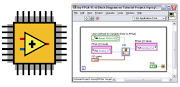
The LabVIEW FPGA Module allows LabVIEW to target FPGAs on NI Reconfigurable I/O hardware so scientists and engineers can take advantage of the performance and flexibility of FPGAs without needing to learn the low-level design tools. Therefore, the basic components of a LabVIEW FPGA system are the LabVIEW FPGA Module, the NI-RIO driver, and an NI-RIO device, also known as a RIO target.
Instructors: Point out the LabVIEW FPGA chip logo. This helps users know if they have LabVIEW FPGA installed – seen on LV Startup page. This symbol will also be used in subsequent slides to represent the LabVIEW FPGA module.
LabVIEW FPGA Module
- Add-on module for LabVIEW
- Develop VIs for FPGA target
- Develop VIs for host PC or Real-Time interaction with FPGA
LV FPGA module is add-on module for LabVIEW. Using the LabVIEW FPGA Module, you can develop custom control and measurement hardware without any prior knowledge of hardware description languages or board level hardware design. VIs created with the LabVIEW FPGA module can be targeted to the FPGAs on NI Reconfigurable I/O, or RIO, hardware. You can also create VIs for your host PC to interact with the FPGA target.

Instructor note: This course focuses on LabVIEW FPGA programming techniques for CompactRIO, Single-Board RIO, and R Series applications. Students who are using FlexRIO typically will need further learning because of the much faster I/O rates and requirements in FlexRIO applications.
The following NI hardware platforms have a user-programmable FPGA:
CompactRIO is an embedded system that is used for machine control, in-vehicle data acquisition, and portable NVH applications.
The R Series is a family of general-purpose data acquisition devices. There are multiple versions of both PXI and PCI and include analog I/O and digital I/O.
The Compact Vision System (CVS) and 825x can acquire data from up to three IEEE 1394 FireWire® cameras and the CVS is a complete system for machine vision applications. This system also includes 29 digital lines whose functionality can be configured using LabVIEW FPGA.
FlexRIO is a target which allows you to create a custom device with user-defined I/O.
RIO Instruments are FPGA-enabled instruments such as the PXIe-5641R – which is a PC-based Intermediate Frequency (IF) transceivers that is used in RF dynamic tests, Software-Defined Radio (SDR), and user-defined IF applications.
Make sure that students realize that LabVIEW FPGA is not a general-purpose FPGA design tool for targeting standalone FPGAs. If users need more flexibility in defining the I/O, they should look into using the FlexRIO system.

The LabVIEW FPGA module compiles your LabVIEW application to FPGA hardware through a compile process. Behind the scenes, your graphical code is translated to text-based VHDL code. Then, industry standard Xilinx ISE compiler tools are invoked and the VHDL code is optimized and synthesized into a hardware circuit realization of your LabVIEW design. This process also applies timing constraints to the design and tries to achieve an efficient use of FPGA resources (sometimes called “fabric”).
A great deal of optimization is performed during the FPGA compilation process to reduce digital logic and create an optimal implementation of the LabVIEW application. Then the design is synthesized into a highly optimized silicon implementation that provides true parallel processing capabilities with the performance and reliability of dedicated hardware.
The end result is a bitstream that contains the programming instructions LabVIEW downloads to the FPGA target. When you run the application, the bit stream is loaded into the FPGA chip and used to reconfigure the gate array logic. The bit stream can also be loaded into nonvolatile Flash memory and loaded instantaneously when power is applied to the FPGA target. There is no operating system on the FPGA chip, but you can control the FPGA chip through a host application.
1. Graphical LabVIEW FPGA code is translated to text-based VHDL code
•Applies timing constraints on the circuit design
•By default, the FPGA clock runs at 40 MHz
2. Xilinx ISE compiler tools are invoked
•VHDL code is optimized
•Logic is reduced
•Gate array configuration is synthesized
3. Bit stream is loaded into the FPGA
Benefits of a LabVIEW FPGA System
- FPGA technology
- No Verilog/VHDL coding or board design
- Onboard decision making
- Direct access to hardware terminals
- Extensive library of built-in functions
- Integration with 3rd party IP
- Tools to communicate, monitor and control the FPGA from Windows PC or Real-Time controller
Besides all the benefits noted earlier of using FPGA, LabVIEW FPGA provides the following additional benefits:
Use LabVIEW to develop your FPGA custom hardware without VHDL coding or board design.
Onboard decision making—You can make control, digital filtering, and Boolean decisions on the target.
Through the LV block diagram, you have direct access to the hardware terminals.
LabVIEW has an extensive library of built-in functions (FFT, Filters, signal generation, etc.). There are tools to integrate with 3rd party IP.
Use the LabVIEW environment and LabVIEW VIs to communicate with, monitor, and control the FPGA from a host PC or a real-time controller. Furthermore, LabVIEW FPGA handles many operations that are not natively handled on FPGAs – such as DMA transfers to the processor, Ethernet communication for CompactRIO, data storage with special CompactRIO modules, and user interface interaction

Example showcasing the high level of abstraction, comparing the implementation of a DMA FIFO (way to transfer data from RT to FPGA) in LabVIEW FPGA vs. the traditional low-level VHDL code and expertise necessary. This middleware alleviates the programming challenge.

The application software running in Windows or a Real-Time operating system (RTOS). For you, this would be the LabVIEW Development Environment.
The driver software and functions to interface to your hardware. This would be the NI-DAQmx driver.
And finally, the I/O hardware. For this specific example, we are calling out an M-series DAQ device.
With this paradigm, end users receive only the functionality that our developers designed into the ASIC of the M Series. Additionally, an extensive driver is required to make all of the device functionality accessible through software. The drawback to this approach is that all of the device functionality is fixed. The customization of such systems comes through the programming at the application software layer which can result in limitations of the hardware functionality and complex software driver calls to perform particular tasks.

When using a LabVIEW FPGA-based measurement system, the paradigm changes. While you are still using COTS hardware from National Instruments, in this case the R Series DAQ device, you can now modify the hardware functionality of this device using LabVIEW FPGA. On the RIO hardware platforms, the FPGA (instead of an ASIC) defines the device functionality. You still have the application software running in Windows or on an RTOS, however, now there is a very thin driver called NI-RIO that provides the interface functions to our hardware. With this paradigm, end users have an I/O platform with the performance, flexibility, and customization of an FPGA without the added complexity of having to understand FPGA and board-level hardware design.

Many test and control systems perform calculations in software. When executing in software the calculation must be performed after multiple software calls through the application software, driver API, and operating system before actually interfacing with the unit under test (UUT). Even when using an RTOS and optimized algorithms, the fastest response rate you can typically achieve in software is around 25 µs. Additionally, there is added vulnerability within a software-based system because a crash can occur at multiple levels that interfere with the response of the system.

When executing calculations in hardware, as with LabVIEW FPGA, you can remove software from the required response to the UUT. Under this configuration, LabVIEW FPGA can respond to digital signals within a single clock cycle. With a default clock rate of 40 MHz, LabVIEW FPGA can respond to a digital signal within 25 ns. You can compile LabVIEW FPGA code at higher rates in some cases.
Performing calculations in hardware provides the highest reliability possible because any crash at any software layer will not affect the execution of your code.
Summary—Quiz
1.Which of the following are required software components of a LabVIEW FPGA system?
a.NI-RIO driver
b.DAQmx driver
c.LabVIEW Development System
d.LabVIEW Real-Time Module
e.LabVIEW FPGA Module
2.What OS runs on the FPGA?
a.LabVIEW FPGA
b.MicroLinux
c.Unix
d.VxWorks
e.None of the above


0 Comments